NUE-PSK Digital Modem

"USB+RTCC" Add-On Card

Optional USB card for NUE-PSK modem records & saves
digital QSOs to flash memory stick for archival and printing.
RTCC circuits on the USB card allow modem to display current date & time.


 Features   |   Design Description   |   Using the USB Card    Schematic   |   Parts List   |


  |  Installing the USB Card  |  Programming the USB Card (early rev's only)  Hardware Mods (early rev's only)  |  Chassis Mods  |


USB Card Manual  |  USB Quick Assembly Guide  |  RTCC Upgrade Guide  |


| ORDERING |

Overview


Need a way to save the text from your digital mode QSO for archival or hard copy printing?  Or perhaps need an official printed record of "Health & Welfare" radiograms handled at a disaster site?  If so, this USB card option will allow you to do just that ... and more!


In a nutshell, the USB add-on card will make your NUE-PSK Digital Modem more flexible and useful with its ability to record QSO receive and transmit text to a USB flash memory stick for archival and remote printing.  The USB card also provides a way to load new modem software from a flash memory device or from a serial USB connection to a PC, and a real-time clock/calendar function to display date & time to the LCD and timestamp QSOs. The updated modem software contains the new keyboard commands for controlling the USB card functions, plus a wonderfully-revamped and consistent text editing commands.


The USB card fits into the existing modem enclosure with minimal modifications. The card occupies the battery compartment, since most users let us know that they would gladly sacrifice the use of internal batteries for this USB capability.  (Battery operation of the modem is also a cool feature and it can indeed run up to 8 hours on a pair of 9V batteries, but we found that most people use the modem with an external source that also powers the transceiver.)


USB Card (top and bottom views) on the left .........  NUE-PSK modem with the USB ports accessible on card plugged into left side of the modem
(Click on photos for larger view)

 
NUE-PSK modem with the USB ports accessible on the left side of the enclosure
The "Type A" connector is for USB stick and USB printer use.  The "Type B" connector is for connection to a PC for loading new software. One can either cut the required holes in the existing bottom half of the modem enclosure, or exchange it with us (for a small fee) for one that is professionally and accurately punched/drilled.


USB Card Features ...

 1) REC MODE -- Records QSOs to a USB flash memory device.   The Ctrl-U command toggles REC mode on to save all incoming and outgoing text from the QSO to the "thumb drive" plugged into the rectangular USB port on the side of the modem.  Additional commands allow you to specify the name of the file being recorded on the flash device, as well as provide the ability to insert additional information to the file as explanatory text for the QSO (e.g., date/time, event, etc.).


 2) FLASH BOOTLOAD -- Loads new modem software from a flash device.  When activated from the menu under the Select pushbutton, this function allows you to "bootload" a new software hex file from the flash device to the modem processor.  A suitable hex file is provided on this website and all you need to do is download it to your flash device, insert it to the modem USB port, and select the Flash Bootload operation from the Select menu.  This operation eliminates the need to connect a serial adapter to P4 on the modem when upgrading the software.


 3) PC BOOTLOAD -- Loads new modem software from a computer.  This new capability allows you to connect the modem to a USB port on the PC using a suitable cable, and upgrade the modem software from the PC.  In effect, this function serves as a built-in serial adapter, thus eliminating the need for using a separate serial adapter for upgrading the modem software.  Just dial up this function in the Select menu, activate the same "prog" program on your PC as before, and watch your modem software get upgraded.


 4) CONFIG UPLOAD+DOWNLOAD -- Sends (uploads) your modem's current settings and macro text strings to a file called config.txt on the USB thumb drive plugged into the modem, and loads (downloads) the config.txt file from the USB thumb drive and puts the settings and macro strings into the modem.  This is a handy pair of features that essentially allows you to edit the settings and macro strings on a PC and them transfer them to the modem.  Thus you will always have a record of your modem's settings and macros and an easy way to tweak them, for example instead of needing to re-enter an entire string using the modem's keyboard.


5) Real Time Clock Calendar (RTCC) -- Once the RTCC components are added to the USB card, the modem's dsPIC controller is able to read the date and time and display this information on the main LCD.  The USB+RTCC card has an onboard battery to enable the RTCC chip to "keep working" even when the modem is turned off.  Then when the modem is turned on again, the current date is once again displayed.  The v3.0 software also allows partial RTCC function even when the USB card or RTCC components are not present.  In this case, an elapsed time counter is presented on the display and again saved to the QSO file on the USB thumb drive in REC mode.


Design Notes ...

     The USB board plugs into the main board by means of a mating female connector to the modem's P4 "Field Programming" pinheader.  Minor and easy mods are required on the modem pcb to supply 5 volts to the P4 connector (instead of 3.3V), and to bring two extra control lines out to a new connector that plugs into the USB card.  The USB card is the same y-dimension as the modem board, and it extends 1-1/8" in the x-direction over to the left edge of the enclosure.  The board sits even with the main board, supported by two standoffs on the left side and a 4-position SIP female header on the bottom that extends out the right side of the board to plug into the existing P4 connector.

     The heart of the design is the Vinculum VNC1L FTDI controller chip.  Although more expensive than "USB bit banging" alternatives, the VNC1L chip provides support for the full USB protocol control, and a DOS-like command line interpreter that allows easy writing and reading of a flash disk, making it a relatively easy design-in for UART ports such as we have available on the NUE-PSK modem.  (For a great overview of the product, see the July 2007 issue 204 of Circuit Cellar magazine www.circuitcellar.com).  Additionally, the VNC1L chip offers Host mode support, which allows the USB card to serve as the "serial interface" to a PC, providing a way to load modem software into the dsPIC as before, as well as providing communications to other devices downstream.

     A real-time clock/calendar (RTCC) function is also provided on the USB card in order to keep track of date and time, even with the power removed from the modem.  The concept is that the PIC monitors the modem's UART port for an "RTCC data request", whereupon the PIC switches data path to send the date and time information to the dsPIC.

Schematic


USB Schematic Rev B1f
(
Download PDF for local printing.)

Parts List


USING the USB CARD

Four main features are enabled by having the USB card installed: REC mode, Flash Bootload, PC Bootload and Real Time Clock Calendar.  These three features are very powerful and will greatly enhance your digital modem experience.

Remember, you must have modem software v3.0 (or later) for these features to work as described ... and you must have firmware "C02" loaded on your USB card.

= = = = = = = = = = = = = = = = = = = = = = = = = = = = = = =
REC MODE -- Records QSOs to a USB flash memory device

Insert a USB flash memory device into the modem connector.  Again, that LED may or may not come on.

Type Ctrl-U on the modem keyboard to place the modem into RECORD mode.  You will see “REC” displayed on the right side of the modem display and the LED on the USB port will start blinking rapidly, indicating that it is ready to receive any text that you may type in Tx mode or any text that is coming across the LCD in Rx mode.  (Note:  If the USB card is not in place, or not working, the REC will be shown briefly on the display and a beep will be sounded by the modem to indicate that an error condition is present.)

Assuming things are working (no beep and the LED blinking rapidly), place the modem into Tx mode (press F10) and start typing some text.  You do not need to be connected to your transceiver to try this out.  You will see the text displayed on the modem LCD of course, but it is also being simultaneously written to your USB flash device.  

Type Ctrl-U again to stop the REC mode and you will see the USB port LED stop blinking and remain on continuously.  

Remove the USB device and plug it into your computer.  You will notice a new file on the stick called NUE-PSK.TXT.  If you open this file you will see the text that you typed while in Tx mode, and any other text that might have been displayed while in Rx mode.

As summarized on the Command Reference sheet, two other USB-related features are available to you.  One is that you may specify your own unique filename for the data being recorded to the USB device while plugged into the modem.  Before turning on REC mode (CTRL-U), you may type CTRL-N and you will be prompted at the top of the modem display to enter a filename.  Give it any standard 8.3 format filename that is useful to you.  (8.3 is 8 characters followed by a period and 3 more characters as an extension, like “Test1234.txt”.) Don’t forget to use CTRL-Z key to end this entry.)

The other USB-related feature is that you may Insert your own text into the data stream being recorded to your USB flash device.  For example, after getting into REC mode (CTRL-U) but before starting up a QSO, you might wish to enter the current date, time or operator name in order to have a better record of the QSO downstream.  To do this, type CTRL-I and you will prompted at the top of the screen to enter this “offline” text.  Don’t forget to end your entry with a CTRL-Z in order to return back to Tx or Rx mode.  Remember, what you enter in this Insert mode is not transmitted, but it is only text that is inserted into the stream of data going to your USB flash memory device.
 

= = = = = = = = = = = = = = = = = = = = = = = = = = = = = = = = = = = = =
FLASH BOOTLOAD -- Loads new modem software from a flash device

This feature allows you to upgrade your modem software from a file placed onto the thumb drive.  All you need to do is place a file containing the latest version of the modem software onto your thumb drive, as downloaded from the NUE-PSK website.  This hex file may then be easily programmed into the processor of your modem.  Thus, you no longer need to use a serial adapter to upgrade your modem software!

If you wish to try out the feature, you could follow these steps ...

1) Download the modem software mem1_33c_img.zip to your computer and unzip it to form the file called mem.dat, and then copy the mem.dat file to your thumb drive. 

2) Insert the thumb drive into the modem and select the Flash Bootload function in the modem menu underneath the Select pushbutton. (Hold the Select pushbutton down for more than 1/2 second and turn the dial counterclockwise until Flash Bootload is displayed.) 

3) Press the Select pushbutton and see "Abort" displayed beneath Flash Bootload.  Turn the dial one notch to see "Start Bootload" displayed. 

4) Ensuring that your thumb drive is inserted, TAP the Select pushbutton and in about 15 seconds your modem will reboot and start up the software version you just loaded.
 

= = = = = = = = = = = = = = = = = = = = = = = = = = = = = = = = = = =
PC BOOTLOAD -- Loads new modem software from a flash device

This feature allows you to load a new version of a software hex file onto your modem from your PC, much in the same way as you did previously when using a serial adapter.

To use this feature, you follow these steps ...

1) Download the latest software to your 
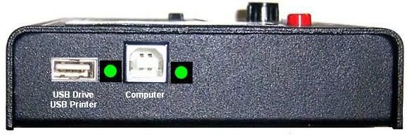
computer, and then connect your modem to the USB port on your PC.  You will use a suitable cable that plugs into the square USB jack on the modem and into the rectangular USB jack on the PC. When you plug in both ends of the cable, the computer will recognize the USB port

2) Ready your PC (in the same fashion as done previously when using the separate serial adapter) by bringing up a Command Prompt window on the PC, navigating to the location where the PROG program and your modem software hex file reside (the root of the C: drive is convenient), and type:
                    prog  -i  com5  modem1_xx.hex
where the COM port number is that used by your PC for the USB ports, and modem1_xx.hex is the specific filename you are going to load per the latest release.  Do not hit <Enter> yet until you have readied the modem side of the connection.

3) Select the PC Bootload function in the modem menu underneath the Select pushbutton.  (Hold the Select pushbutton down for more than 1/2 second to bring up the menu and turn the dial counterclockwise until PC Bootload is displayed.) 

4) Press the Select pushbutton and see "Abort" displayed beneath PC Bootload.  Turn the dial one notch to see "Start Bootload" displayed. 

5) Press the Select pushbutton then hit the <Enter> key on the PC keyboard to run the PROG program.  You will see the standard series of about 100 dots appear on the PC screen to signify the program download process.  When the dots stop appearing, the modem will reset and the new software will be running.

NOTE:  You will need to have the FTDI USB driver installed before attempting to use this PC Bootload feature.  To install the driver,  download the driver installation zip file,  expand it onto a temporary file on your PC, and then plug in the cable from your modem.  With the modem power turned on, the PC will recognize that a new USB device is plugged in and Device Found Wizard will pop to lead you through the process of installing the new driver.  At the appropriate point indicate that you wish to specify that that PC searches for the driver at the location you have the temporary folder.  When the PC indicates that the device is successfully installed, you can use the PC Bootload feature.  NOTE:  If you need help with this process, you can download and study the FDTI application note called "AN232R-03 Driver Pre-Installation Document."

= = = = = = = = = = = = = = = = = = = = = = = = = = = = = = = = = = =
REAL TIME CLOCK CALENDAR -- Maintains accurate date and time on the modem display, and timestamps added to QSO recordings to flash drive.

Once the RTCC components are added to the USB card, the modem's dsPIC controller is able to read the date and time and display this information on the main LCD. The USB+RTCC card has an onboard battery to enable the RTCC chip to "keep working" even when the modem is turned off.  Then when the modem is turned on again, the current date is once again displayed.  The v3.0 software also allows partial RTCC function even when the USB card or RTCC components are not present.  In this case, an elapsed time counter is presented on the display and again saved to the QSO file on the USB thumb drive in REC mode.


Date and time displayed on modem LCD
(Click on photo for larger view)

In receive and transmit modes, the date and time are displayed on the top line of the 128 x 64 graphical display. In other modes, the entire screen is used so the date and time are not displayed; however, the date and time are maintained so they will be current when next displayed. When first powered up, the time is initialized as “00:00:00” and the date is not displayed until the date is input to the modem either by the operator (see Configuration Menu) or by the optional USB option card (automatic, if installed). If the time is not updated, it can serve as a running time meter showing how long the modem has been turned on. The operator may also choose to turn the date and time displays off.

The date display is located in the upper left corner as an eight-character string formatted as:  “MM/DD/YYYY. The time display is located in the upper right corner as an eight-character string formatted as:  “hh:mm:ss” in a 24-hour format. To conserve display space, both are displayed using a special 3 x 5 font with no space between characters instead of the standard screen font which is a 5 x 7 font with one column of pixels between characters (6 x 7 pixels used per character).

The time is updated every second either by the Real Time Clock Calendar (RTCC) circuits on the USB option card or, when the USB option card is not installed, by a one-second timer in the modem. The main differences between these two approaches are accuracy and persistence. The RTCC on the USB option card uses the same type of crystal used in quartz watches to generate a very accurate time base.  The modem time base is derived from the main system clock and is less accurate. The RTCC is powered by its own separate battery so it will maintain accurate time even when the modem power is turned off. Each time the modem is turned on, it verifies that the RTCC is present and automatically sets its copy of the date and time from the current RTCC settings. When the RTCC is not detected, the user must manually enter the date and time each time the modem is powered up.

When the USB option card is first installed, the date and time settings will not be accurate. The operator must enter them once. From then on, the RTCC will maintain them whether or not the modem is powered on.  The RTCC knows nothing about time zones and daylight savings time. The operator can choose to use either local time or Universal Time and must change the time ahead or back one hour to account for daylight savings time, if desired. The RTCC programming is aware of leap years so it is not necessary for the operator to make leap year adjustments in the date. Of course, the operator will have to reenter the 
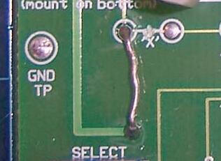
date and time after replacing the RTCC battery. (Note:  Whenever a battery is installed onto the USB card, pin 4 of PIC controller U3 should be grounded quickly once with a touch of a clip lead in order to properly reset the PIC and start the clock programming.)

Timestamping REC files

The QSO recording format for flash drives is enhanced with additional information including date and time.  At the start of each recording session (initiated by a CTRL-U) the following text block is written to the file:

*****************************************

* START RECORDING  <MM/DD/YY hh:mm:ss>  *

*****************************************

This text block is always followed by a blank line.  At the end of the recording session (terminated by another CTRL-U), the following text block is written to the file:

****************************************

* STOP RECORDING  <MM/DD/YY hh:mm:ss>  *

****************************************

This text block is always preceded by a blank line.

The start of each recorded receive session contains the following preamble text:

* * * RECEIVING:     <hh:mm:ss>

This text is followed by a single space character and then the received text as received, no formatting.

The start of each recorded transmit session contains the following preamble text:

* * * TRANSMITTING:  <hh:mm:ss>

This text is followed by a single space character and then the transmitted text as transmitted, no additional formatting.

When the operator inserts text in the recording (CTRL-I), the following text is inserted in the file:

* * * INSERTING:     <hh:mm:ss>

This text is followed by a single space character and then the operator-keyed text, no additional formatting.  When the operator ends the insert operation with CTRL-Z, the modem resumes recording the interrupted mode with the appropriate RECEIVING or TRANSMITTING preamble.


INSTALLING the USB CARD

You may skip this entire section if you purchased the "full factory upgrade" for your USB card.

Otherwise, you will need to install your modem card into your modem, as outlined in this section.  In doing this, you will need to make a simple modification to your modem's pc board and add a thin 3-wire cable to extend some signals over to the USB card.

1) Ensure that pads 4 and 5 are shorted on the 8-position programming pads on bottom of the USB card. Original USB cards purchased before June 2009 had an 8-position pinheader attached, and this should have a shunt (jumper) installed between pins 4 and 5, or even just a wire jumper soldered between the pads such as done on kits and assembled cards purchased since then.  See the photo at the bottom of the page that illustrates the proper position of the shunt.

2) Open up the modem enclosure and remove the modem pc board by removing the four standoff screws from the bottom chassis.  Snip off the two pairs of wires of the battery clips. (You will no longer be able to use the internal battery capability.)

3) Add 5V jumper on modem board at Field Programming port P4. First cut the ‘X’ trace connecting the two pads near the lower-left LCD standoff. (Make sure this 3.3V trace is thoroughly cut.) Next add a short jumper from the leftmost ‘X’ pad to the pad above the Select pushbutton.  This jumper will supply 5V to the USB card.

4) Attach a 3-wire Control cable to modem pc board. On the modem board, remove the top four screws holding down the LCD the and lift up LCD. Solder a 4" three-wire ribbon cable to points ‘a’, ‘c’ and 'd' on the modem board right next to U1, as shown in the photo below.  The other end of the cable should have a 3-position 0.1" socket soldered to it such that it can be plugged into the 3-position pinheader P3 on the USB card.  The (green) wire coming from pad 'd' should go to the innermost pin 3 on P3, and the (orange) wire coming from pad 'c' should go to the middle pin 2 of P3, and the (yellow) wire coming from pad 'a' goes to pin 1 closest to the USB card edge.

   
3-signal control cable connects pads a, c and d to USB card
(Click on photo for larger view)

5) Use the hole template to make holes in existing bottom chassis for USB connectors and LEDs, or use the optional pre-drilled replacement chassis.

6) Load the latest software into your modem.

7) Plug the USB card into the Field Programming port P4 along the modem board’s left edge and attach the 3-wire "Extra Signal cable" to P3. Plug the single wire coming from the CTS pad on the back of the USB card into the third position of the Extra Signal Cable socket.

8) Insert the modem board into the new/modified chassis and screw into place. Proper clearance for modem board controls can be achieved by biasing board to lower left while tightening top and bottom screws.


Chassis Mods:
Use this template to cut the holes required for fitting the USB card into the black aluminum chassis.  Instead, you may purchase a pre-milled replacement chassis ... see the Ordering page for this option.


Download PDF version of the DIMENSIONS diagram
or
Download a JPG version of the actual TEMPLATE suitable for placing on the end panel and drilling

Back to the NUE-PSK Home Page


PROGRAMMING the USB Card ... Only needed for earlier-model USB kits!

You may skip this entire section if ...

  1. If you purchased the USB Card already assembled & tested; or

  2. If you purchased the assembled USB card option when you ordered the assembled modem; or

  3. If you purchased your USB Kit after June 2009 (since this date we have been providing pre-programmed USB chips in the kits); or

  4. If you had us do the "full factory upgrade" for your modem.

Otherwise ... you will need to follow the instructions below to program software into the U1 chip on the USB card.

1) VDPSFUL_V3_66_C02.ROM — This is the file that needs to be placed into the VNC1L chip (U1) on your NUE-USB card.  It contains the firmware program that makes that U1 chip “smart” and able to talk to the USB flash memory devices that we plug into our card.  NOTE:  You must have the latest modem software (v1.33c or later) loaded on your modem in order to use the USB card.

2) VPROG.COM – This is the program used to place the ROM file (above) into the U1 chip on the USB card.  It’s a simple application program run on your PC ... just connect your PC’s serial port to the 8-position programming header you soldered onto the bottom of the USB card, per the dotted line insert in the lower left of our USB schematic.  I’ve shown the connections needed to allow the popular CP-2102 USB-to-TTL adapter that many of us are using, but any adapter may be used that proves the standard RxD, TxD, CTS and RTS signals from the serial port.  (Don’t forget to put the jumper from the GND pin to the PROG pin on that connector, as this is the signal to the U1 bootloader that a new file is coming to it.)

When you run the VPROG program (e.g., just double-click the filename from your Windows Explorer window), a small window will appear with a couple of items you need to specify ... the number of your serial port, and the ROM file you wish to program into our U1 chip.  (Just browse to the ROM file you downloaded and select it.)

Then click “program” -- if your USB card was assembled correctly, and if you have the PC serial port wired correctly to the 8-pin programming header, you will see a progress bar displayed on the PC screen showing that the U1 chip is being programmed, and then verified.  This only takes about 15 seconds to occur.  

Remove the serial adapter and cable from your card and place a shunt (jumper) on pins 4-5 of that same 8-position pinheader on the bottom of the USB card.  (See photo at bottom of this page.)

You are now ready to install the USB card into your modem!

NOTE:  Easy Upgrade from A01 to C02 USB Firmware:  If you previously had "A01" or "C01" firmware programmed into your USB card (done either by you during kit assembly, or by us here at the factory), here is a super easy way to load the newer "C02" firmware ...

1) Download the C02 firmware to your PC and unzip the file.  The file FTRFB.FTD will be extracted and you should copy this from your PC to your thumb drive.

2) Insert the thumb drive to the modem, turn on the power, and wait a few moments.  The USB card will recognize the presence of the FTRFB.FTD file on the thumb drive and it will reprogram itself (!!)  [Note:  The modem must be powered on with the thumb drive already inserted.]

3) Important:  Remove the thumb drive, and using your PC, delete the FTRFB.FTD file from the thumb drive ... Otherwise, you will always be reloading the C02 firmware to the USB card.


PCB Change Needed on Original-issue USB Cards (only for USB cards purchased prior to June 2009)

If you have one of the original-issue USB cards purchased before June 2009, you will need to add two resistors to the main connector and a jumper on the square USB connector.  (The resistors and jumper are already included on the "rev A4" that started shipping then.) Also, if you received an assembled and tested USB card (or factory upgrade) since then, you do not need to perform these modifications.  The changes are easy to do and will ensure that you have the best hardware for successful use.

Using the photo below, make these changes to your USB card ...

1) Add jumper wire from CN1 pin 4 to the adjacent ground pad;

2) Add a pull-up resistor to the TxD and RxD pins of the female connector;

3) Ensure that a shunt (jumper) is installed on pins 4 and 5 of the 8-position pinheader.

Bottom view of the USB card showing modifications to be made
(Click photo for a larger view)


Page last updated:  Dec 14, 2011