NUE-PSK Digital Modem
Making a Serial Cable
![]()
How to make a simple cable connecting your Serial Adapter to the modem
|
|
NUE-PSK Digital Modem Making a Serial Cable
How to make a simple cable connecting your Serial Adapter to the modem |
|
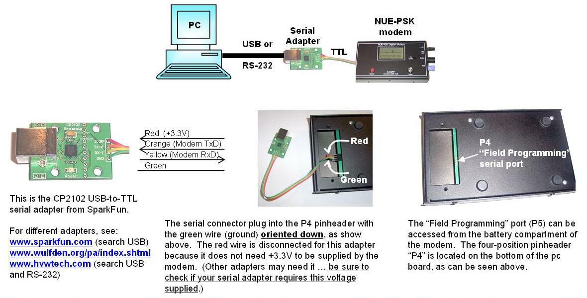
You'll recall from our literature that the NUE-PSK Digital Modem may be upgraded to newer software in the field (that is, by *you*) simply by connecting the serial port of your PC to an adapter, which in turn plugs into the "Field Upgrade" connector in the battery compartment of the modem. Then with the proper program running on your PC (available for free download from the NUE-PSK website) you can send the modem the latest-and-greatest software we supply on this NUE-PSK website. This is a great way to keep your modem up to date with the latest features and bug fixes!
See the Refresher Tip at the bottom of this page for some guidance on where you can get the appropriate serial adapter for your computer.
The USB or RS-232
serial interface adapter that you do get will probably need a cable to
connect it to the modem's "Field Programming" port -- the 4-pos'n, 0.1"
pinheader "P5" on the bottom side of the modem pcb, as accessed from the
battery compartment. You can fabricate a simple four-wire ribbon
cable terminated on one end in a mating SIP connector (Mouser
p/n 517-974-01-04, as shown on catalog page
http://www.mouser.
If you wish to purchase the serial cable from us, you may do so on our main Order page. However, if you decide to make your own cable, it would end up looking something like this ...
.JPG)
Homebrew 4-wire serial interface cable
.JPG)
Homebrew
4-wire serial interface cable attached to a SparkFun USB-to-TTL adapter
Black 4-pin connector on end of ribbon cable plugs into the NUE-PSK
serial "Field Programming"
port at P5 pinheader on underside of modem pcb, as accessed from the
battery compartment.
Easy changes needed for using HVW Technologies RS-232 Adapter
1) The Tx and Rx connections to the HVW adapter board need to be swapped, as compared to the SparkFun adapter example shown above. That is, when using the serial cable we provide, the wire colors should be connected to the HVW board as follows:- Green-> Organge<- Yellow+ Red2) The HVW board requires 5V to power it. So, different from the example we showed with the SparkFun adapter, you must have the red wire connected to the black 4-pos'n connector on the end of the serial cable. Then (important), you need to modify the NUE-PSK board slightly (it's easy) to supply 5V to P4 pin 1, instead of the 3.3V that it supplied by default. Just cut the trace labeled "X" on the top of the pcb near P4p1, and add a short jumper from small hole above the silkscreen label Select (by the pushbutton) over to the the pad with the trace leading to P4p1. This jumper will supply 5V to P4p1 and power the HVW board.
.JPG)
HVW Technologies RS-232 adapter with the NUE-PSK Modem
Note the cut in the X trace, the jumper to the 5V hole, and the
swapped red/yellow wires.
(Click for bigger view.)
Checking out the Serial Interface
So you just got one of those nifty serial interfaces from Wulfden, SparkFun or HVW Technologies in order to load up new software for your NUE-PSK Digital Modem ... and you're wondering "How do I know if this thing works?"
So here is a way to test your serial adapter by establishing a serial connection to your PC before you actually load the latest version of modem software into the box.
What we describe here is a way you can use your serial interface (either the USB-to-TTL version or the RS232-to_TTL version) to read program memory from the modem and display it on your PC. Then if you see the standard/typical display of addresses and data, you can rest assured things are cool and you will be able to load new software into the modem when the time comes.
The technique is similar to what is described in the NUE-PSK modem manual for updating modem software, but instead of specifying the name of the hex file we just enter the -p option on the command line. This command line option for the prog program reads from program memory and displays the results to your PC display.
First, you'll need to "get ready" by first doing a couple of things ...
1) Determine what COM port number your USB or RS-232 serial port is -- You can find this out by clicking START and then right-clicking My Computer. Select Properties and then the Hardware tab. Click Device Manager and find the Ports line item in the list. Expand that line item and see that the Communications Port will have a COM number shown. That is the serial COM port number that you'll use.
2) Get the PROG program onto your local computer -- You can download prog from here. Save the file in a convenient place, like at the root of your C drive. (When your computer prompts for the save location, enter C:\ )
So, now that you are ready, next perform the following steps to connect the PC to your modem using your serial port ...
3) Connect the serial interface between the NUE-PSK modem programming port and the PC -- You will typically need to connect your serial adapter to a serial port cable that is plugged into your computer, and then connect the adapter to the 4-position "Field Programming" pinheader (P4) located on the bottom side of the modem pc board, as accessed form the battery compartment.
4) Open a Command Window on the PC -- You can bring up this window by clicking in START, Run ... and enter Command. Navigate to where you saved the prog.exe program. If this was at the root of the C drive, just enter CD \ .
5) Enter command to run the "prog" program -- From the prompt inside the Command Prompt window, type the following command line ... but do not yet press <Enter>. For example, on my system that uses COM1 serial port, I would type .... prog -i com1 -p 0x000400
5) Power up the modem in a special way -- Hold down the "Select" button on the Modem, while turning on the power switch. This commands the modem to look to the serial port for about 10 seconds before it continues powering on normally. Then quickly, within these 10 seconds of turning on the modem, press the "Enter" key on the PC keyboard to execute the command you previously entered.
6) See the PC screen start displaying the modem memory contents starting at location 0400 -- Wait for the display on the PC to stop displaying the data, then compare it to the screen shot below. If it is anything like what we show, then you indeed have a fully functioning serial interface! The numbers shown happen to the be the contents of memory locations starting at address 400 in the dsPIC, which is the modem software we programmed into the dsPIC before delivering it to you. (These numbers correspond to version 1.12b software - they will likely be somewhat different for follow-on versions, but the first word at location 400 will probably stay the same as 00000a.)
So if you can indeed see this type of response, your interface is working just fine!
Refresher Tip #1 ... "What's a serial interface for my NUE-PSK modem?
You'll recall from our literature that the NUE-PSK Digital Modem may be upgraded to newer software in the field (that is, by *you*) simply by connecting the serial port of your PC to an adapter, which in turn plugs into the "Field Upgrade" connector in the battery compartment of the modem. Then with the proper program running on your PC (available for free download from the NUE-PSK website) you can send the modem the latest-and-greatest software we supply on this NUE-PSK website. What a great way to keep your modem up to date with the latest features and bug fixes!
Refresher Tip #2 ... "Where do I get one of those serial interfaces?"
Again from the QST and QEX articles, we mentioned that we do not provide a serial interface with the modem purchase because everyone's computer and way of operating are different. There are some great products out there and you can purchase specifically just what you need for about $20 from a number of good vendors. Based on what kind of serial port you have on your computer, you will want to purchase a USB-to-TTL interface or an RS232-to_TTL interface. Of course you could instead homebrew a simple one-IC version of the interface right from the schematic we provide in the manual and in the articles, thus saving you the purchase of the adapter.
Any way you get there, the interface adapters are available from ...
1) Wulfden at Hawk's Mountain -- http://www.wulfden.org/pa/index.shtml
2) SparkFun Electronics -- http://www.sparkfun.com/commerce/product_info.php?products_id=198 (USB)
3) HVW Technologies -- http://www.hvwtech.com/products_view.asp?ProductID=409 (USB), http://www.hvwtech.com/products_view.asp?ProductID=289 (RS-232)
Refresher Tip #3 ... "Serial Connection to the Modem P5 Connector"
The USB or RS-232
serial interface adapter you get will probably need a cable to connect it
to the modem's "Field Programming" port -- the 4-pos'n, 0.1" pinheader
"P5" on the bottom side of the modem pcb, as accessed from the battery
compartment. You can fabricate a simple four-wire ribbon cable
terminated on one end in a mating SIP connector (Mouser p/n 517-974-01-04,
as shown on catalog page
http://www.mouser.
If you wish to purchase the serial cable from us, you may do so on our main Order page. However, if you decide to make your own cable, it would end up looking something like this ...
![]()
![]()
Page last updated: Feb 17, 2009