AmQRP products supplied by Midnight Design Solutions
NUE-PSK Digital Modem
Replacing the Lower Chassis
![]()
Description of how to upgrade your modem with the pre-milled lower chassis that accommodates the optional USB card
|
AmQRP products supplied by Midnight Design Solutions |
NUE-PSK Digital Modem Replacing the Lower Chassis
Description of how to upgrade your modem with the pre-milled lower chassis that accommodates the optional USB card |
|
When you add the USB card option to the NUE-PSK modem, it is necessary to either modify the stock chassis with holes to accommodate the USB card, or purchase a pre-milled chassis and replace the chassis yourself. Although it is a straightforward thing to do, the mechanical tolerances of the various subassemblies "stack up" and one might have trouble aligning the screws for the pc boards ... but there are some tricks that can make the job much easier. This page describes the techniques used here at "the factory" nearly every day when assembling new modems with the USB card option.
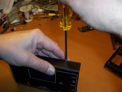
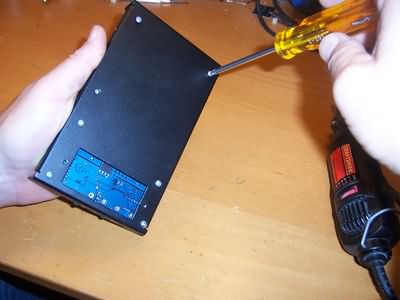
STEP 1: Unscrew the four black screws that hold the cover (upper shell) to the chassis (lower shell). These screws are located on either side of the modem.
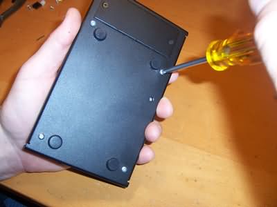
STEP 2: Unscrew the four screws on the bottom of the modem that hold the modem pcb assembly in place.
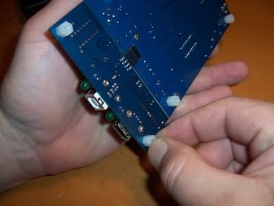
STEP 3: Take the modified modem board (with the 5V jumper in place and the 2-wire signal cable added), and plug in the USB card.
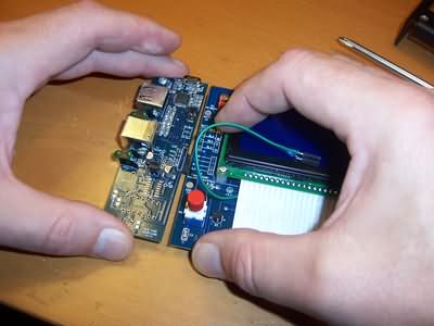
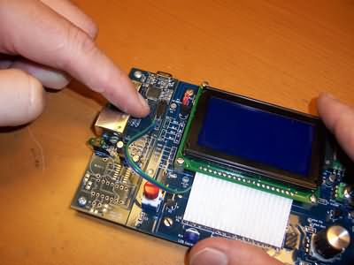
STEP 4: Plug in the 2-wire signal cable to the 2-position pinheader on the USB card. Per instructions, make sure the wire coming from pad 'c' on the modem goes to the inside of the USB pinheader. (It's the green wire in the modem pictured below.)
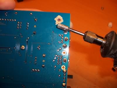
STEP 5: "Making the mod to ground the pc board to the chassis" ... Remove the nylon standoff pictured below.
STEP 6: Grind or scrape the blue solder mask from around the mounting hole, thus exposing the copper foil of the pcb ground plane.
STEP 7: Grind or scrape around the corresponding hole in the new USB-modified lower chassis
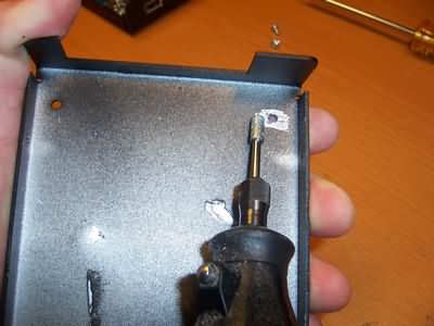
STEP 8: Put a metal standoff in place of the nylon one for that hole. (Contact us if you can't find one in your junk box or local hardware store.)
STEP 9: Slightly loosen all standoffs on the bottom of the pc boards. This is the important step that will give tolerance for mounting the six standoffs again in the chassis.
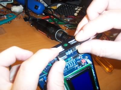
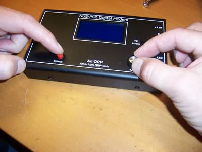
STEP 10: Carefully insert the pc boards into the chassis as shown below, ensuring that the USB connectors go into the mating holes in the side panel of the chassis.
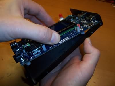
STEP 11: Slightly separate the USB pc board from the modem pc board, with about a 3/32" gap, as shown below.
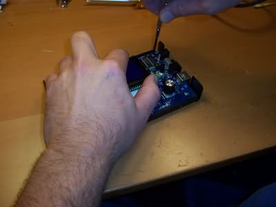
STEP 12: Turn the modem assembly over while still carefully holding the pc boards in place and position the modem board such that you can start screwing in the six silver screws on the bottom. Do not tighten the screws!

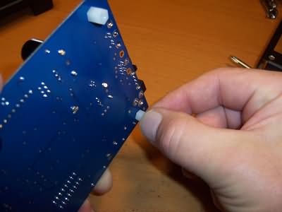
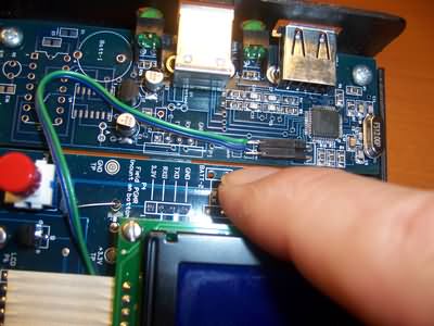
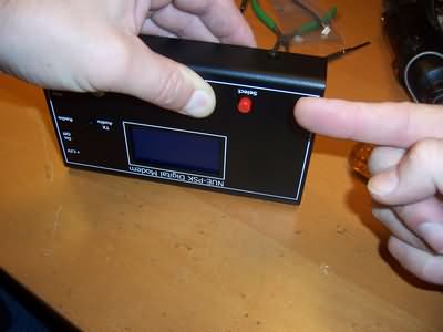
STEP 13: With the modem assembly still loose (it can be noticeably wiggled around), apply pressure to push this loose assembly toward the lower right, as indicated by my finger in the photo below.

STEP 14: Keep this angular pressure (now shown as down to the lower left) by using your left hand, and ...
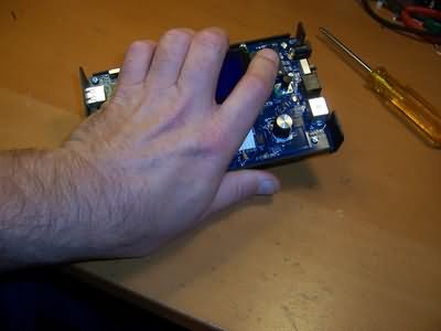
STEP 15: ... and then turn the modem over and tighten the four screws holding the modem pc board only. (Don't yet tighten the two screws holding down the USB card.)
STEP 16: Turn the assembly over again, and now apply counterclockwise pressure with your left hand to slightly move the right corner of the modem up. This action will provide sufficient clearance for the controls when we put the top cover on.

STEP 17: And now with that counterclockwise pressure applied, screw down tight the top four screws of the modem board.
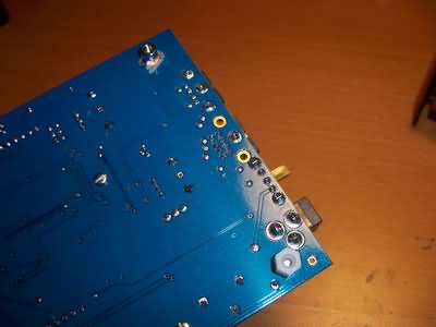
STEP 18: Since the USB card is still loose (top and bottom screws are still loose in the standoffs), position the USB card such that its connectors protrude into the mating holes in the chassis side panel, and that they are flush with the outside of the chassis. They should not stick through.
STEP 19: Notice again how there is still a gap between the modem board and the USB card. This is normal and it was designed to be this way. (Otherwise, it could be difficult to insert the pcb assembly into the chassis!)

STEP 20: Taking care to hold the USB card in place, turn the assembly over and tighten down the two USB holding screws on the bottom of the chassis. Make it tight, but not so tight as to strip the nylon standoffs.
STEP 21: Turn the assembly over and tighten down the top two screws holding down the USB card.

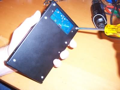
STEP 22: Position the top cover on the assembly and start the first black screw into the side. But before you tighten it down ...
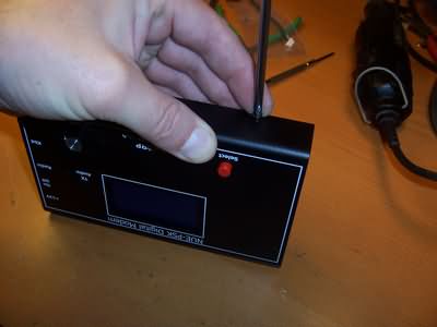
STEP 23: ... apply pressure to the cover with your thumb, sliding it in the direction my finger is pointing in the photo below. Only then, tighten down the screw, and the proceed to attach the other three black screws, all the while pressing the top cover to the chassis with your left hand to ensure a complete mating of the two shells.
STEP 24: If everything was done according to plan, there should be sufficient clearance for the red pushbutton to go up and down unimpeded, as well as for the Tune dial to turn without scraping the side of its hole.
CONCLUSION: I know it seems complicated, but it's really quite straightforward and easy. It takes more to describe it than to do it! But in the end, you will have a properly assembled modem. I've literally done over 500 of these assemblies and it takes perhaps about 2 minutes to do the whole thing. If I get a chance, I'll shoot a video of the procedure for any of you thinking that things just are not lining up properly ;-)
73, George N2APB
![]()
Page last updated: October 27, 2009