NUE-PSK Digital Modem
Installing the Batteries
![]()
"How do you get those two 9V batteries in that little compartment??"
|
|
NUE-PSK Digital Modem Installing the Batteries
"How do you get those two 9V batteries in that little compartment??" |
|
Some people have been finding it difficult to fit the two 9V batteries into the underside compartment of the NUE-PSK Digital Modem. Although it is a bit tight, they do indeed fit!
So we thought we'd share some insight as to why we made the rather unusual decision to use 18 volts as the battery supply, and then show you an easy way to install the batteries in your modem.
Design Background
We chose to use a switching regulator (U9) as the voltage regulator in the modem, instead of using the more conventional 7805 linear regulator to get 5 V on the board. This solution requires a lower operating current from the supply because of the greater efficiency achieved by the switching “buck” regulator. A linear regulator merely dissipates the power difference between input and output in the form of heat. Thus, even though the dsPIC draws approximately 100 mA, the modem now only requires about 60 ma from the supply during normal operation, and portable power is easily provided by conventional alkaline batteries.
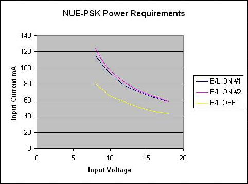
Power requirements for the NUE-PSK modem.
Measurements illustrate the
dramatic benefits of using the switching “buck” regulator. Regulator
efficiency increases as
higher supply voltages are used. The top curves show the input current
requirement when
running with the display backlight on, while the lower curve shows 15 mA
less current when
the backlight is off.
A small drawback of using the switching regulator is that a 9 V minimum input is required to maintain regulation; so battery operation is achieved by using two standard 9 volt batteries in series to provide a nominal 18 volts input to the modem. Of course the digital modem may instead be externally powered by applying anything from 9V to 18V through J1.
See also our Battery Life Study web page.
NOTE: When external power is applied, the plug inserts to the power jack and opens the internal normally-closed switch in J1 and removes the batteries from the circuit, as illustrated in the schematic. (The first 58 units that shipped to the "early bird customers" need to have the pcb modified for operation as described; whereas all later units shipped have this modification made at the factory before being shipped.)
Installing the Batteries
It's really not too difficult to install the batteries once you get the hang of it. As shown in the photos below, the batteries fit "nose-to-nose" in the compartment, with one battery lying flat against the inside "bottom" surface (really the inside of the enclosure's top shell) and pushed all the way over to one side. The second battery is positioned at an angle, with its connector clip resting atop the lower battery's clip, such that they fit together like a hand-in-glove. This way, the vertical depth of the two batteries is minimized and the top cover can be screwed in place without exerting any significant downward force. A little tick is to have the leads from the "upper" battery clip feeding out toward the pcb, as shown in the photos. Then just tuck the battery leads into the enclosure and screw the battery cover in place.
.jpg)
The two 9 V alkaline batteries nestle
tightly against the circuit board in the case
compartment. When installed, the screw-on cover holds them firmly in
place.
(Click photo for full-res view.)
.jpg)
The second battery is positioned at an
angle, with its connector clip resting atop
the lower battery's clip, such that they fit together like a
hand-in-glove.
(Click photo for full-res view.)
.jpg)
.jpg)
Two more views of the batteries in place
(Click photos for full-res
view.)
Video Clip: Installing the Batteries
We have a short 2.5 minute video clip that demonstrates how to install the batteries. It's a rather large file (20 MB), so it might take a bit of time to get started, but it will eventually open in your Windows Media Player and you can have a front row seat in viewing the installation of the batteries.
Good luck and let us know if you have any problems with your batteries.
73, George N2APB
& Milt W8NUE
![]()
Page last updated: April 19, 2008